This is aspect So 18a: point is locked and can be travelled facing.

I have several standard Hp semaphore signals on my layout, but I also have some signals which are not often seen on layouts: East German Hl signals, and a So 18 supervision signal for spring-loaded points.
The Hl signals were made be Modellbau Reinhardt and are of excellent quality. Very unfortunately the company closed end of 2020.
|
|
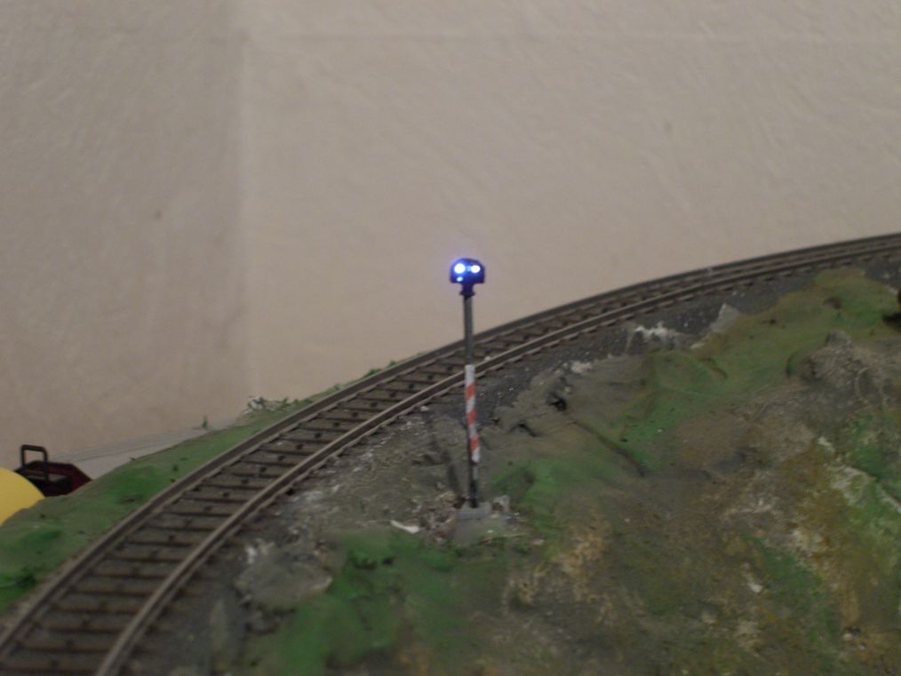
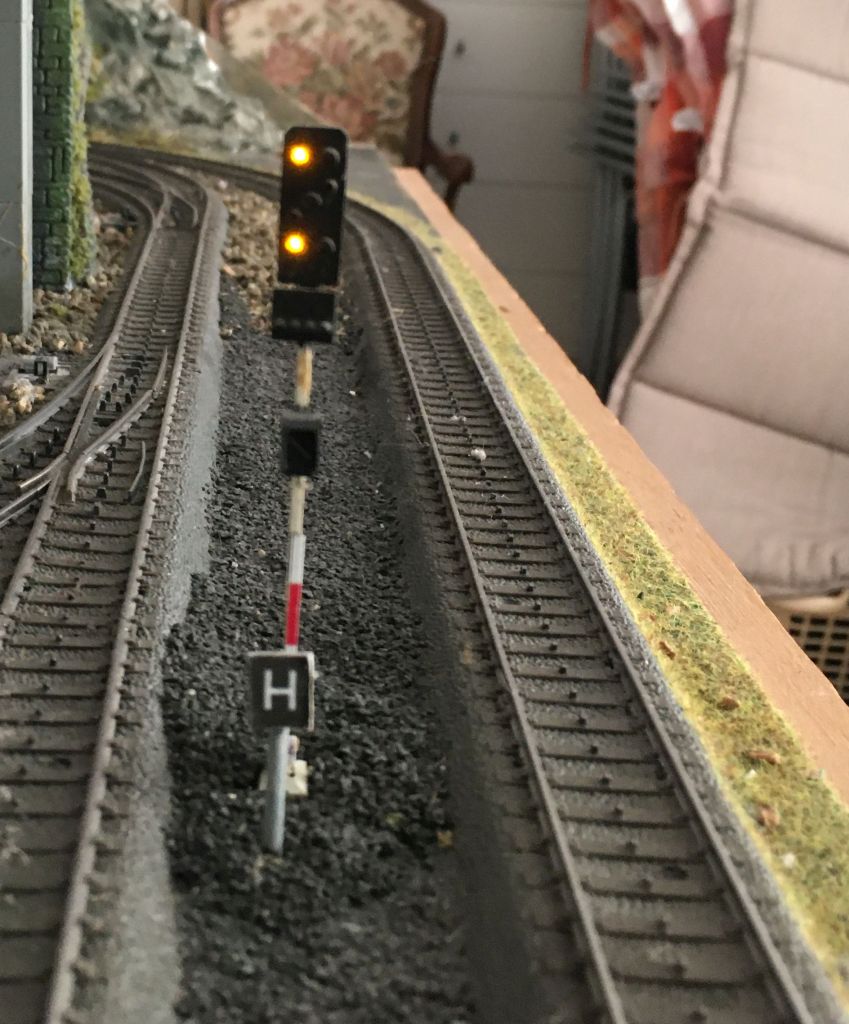
The So 18 was made from a
Viessmann standard Sh 0/1 signal where I exchanged
the two red LEDs for two white ones. This is aspect So 18a: point is locked and can be travelled facing. |
|
|
This is aspect So 18b: point can not be travelled facing. Stop and make sure that point is locked before proceeding. |
I think most of you are familiar with Märklin semaphore signals, so I will give some more details about the Hl signals I use on my layout. Hl signals are special because they are multiple-block signals, i.e. they give a main signal indication as well as indicating the aspect to be expected at the next signal. As you will see in the track plan below, it may depend on the setting of the points which signal is the next signal.
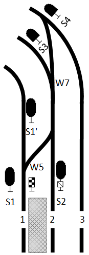 |
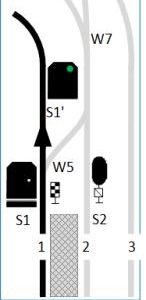
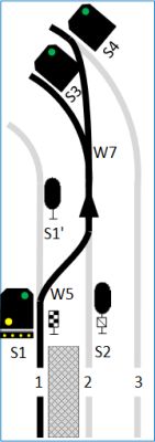
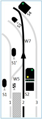
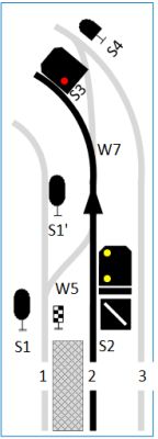
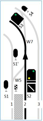
The station is at the bottom, and the platform tracks are no. 1 to the left and no. 2 in the centre. The track no. 3 on the right bypasses the station. The signals are numbered S1, S1', S2, S3 and S4, and the points (German: Weichen) are numbered W5...W7. For the setting of the signals, only points W5 and W7 are important, we assume that the adjacent points are always correctly set. A train exiting from track 1 may exit to T1 (W5 straight), T2 (W5 diverging and W7 straight), or T3 (W5 and W7 diverging). Signal S1 is exceptionally placed to the left of track 1, which is indicated by the chequerboard sign. If the point W5 is set to straight, signal S1' serves as exit signal, so S1 is meaningless and shows a Kennlicht (marker light). |
| exiting from track 1 | |
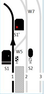 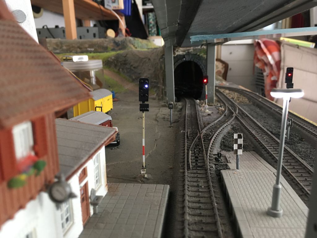 |
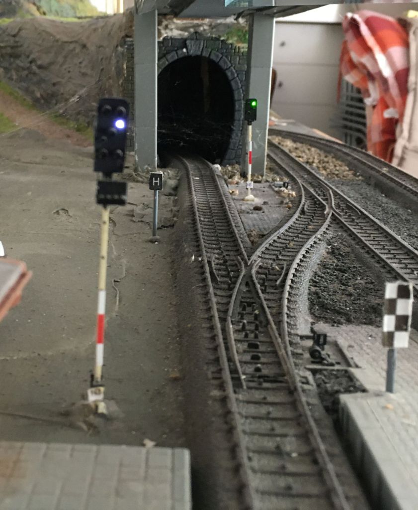
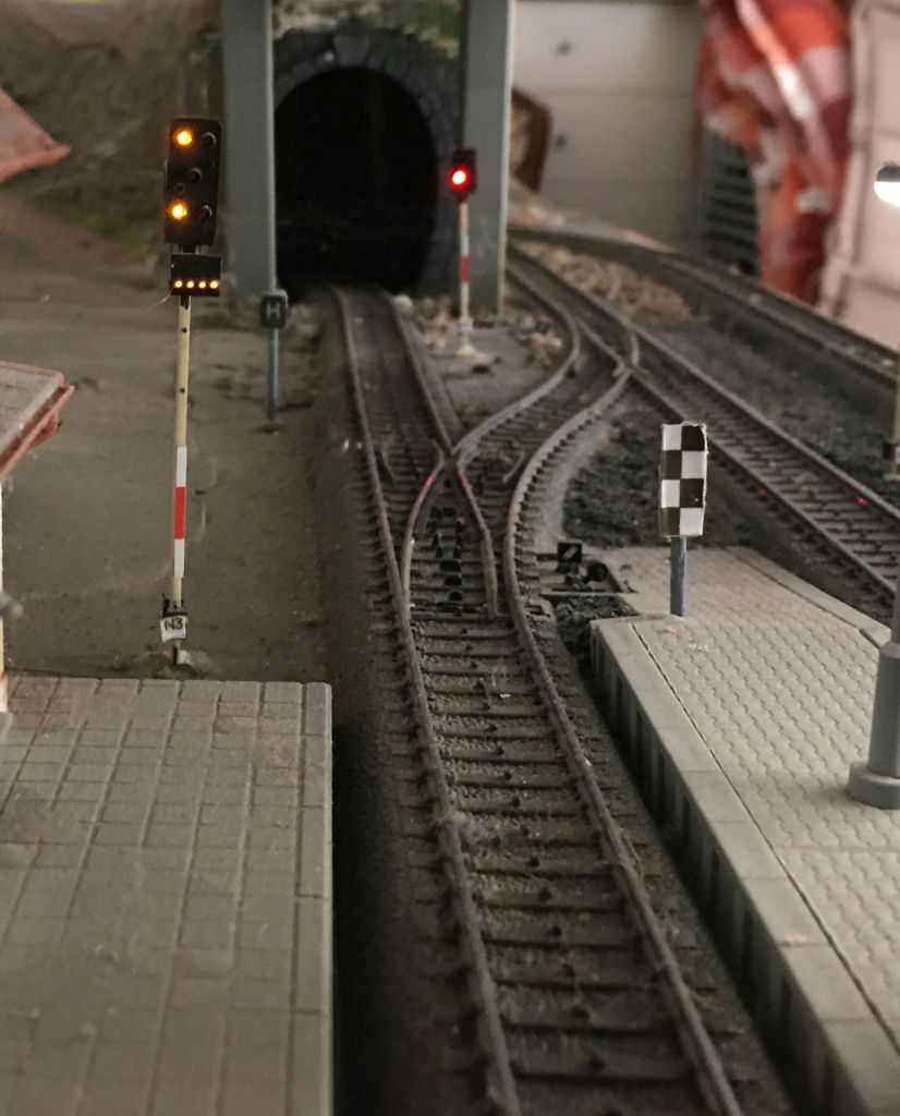
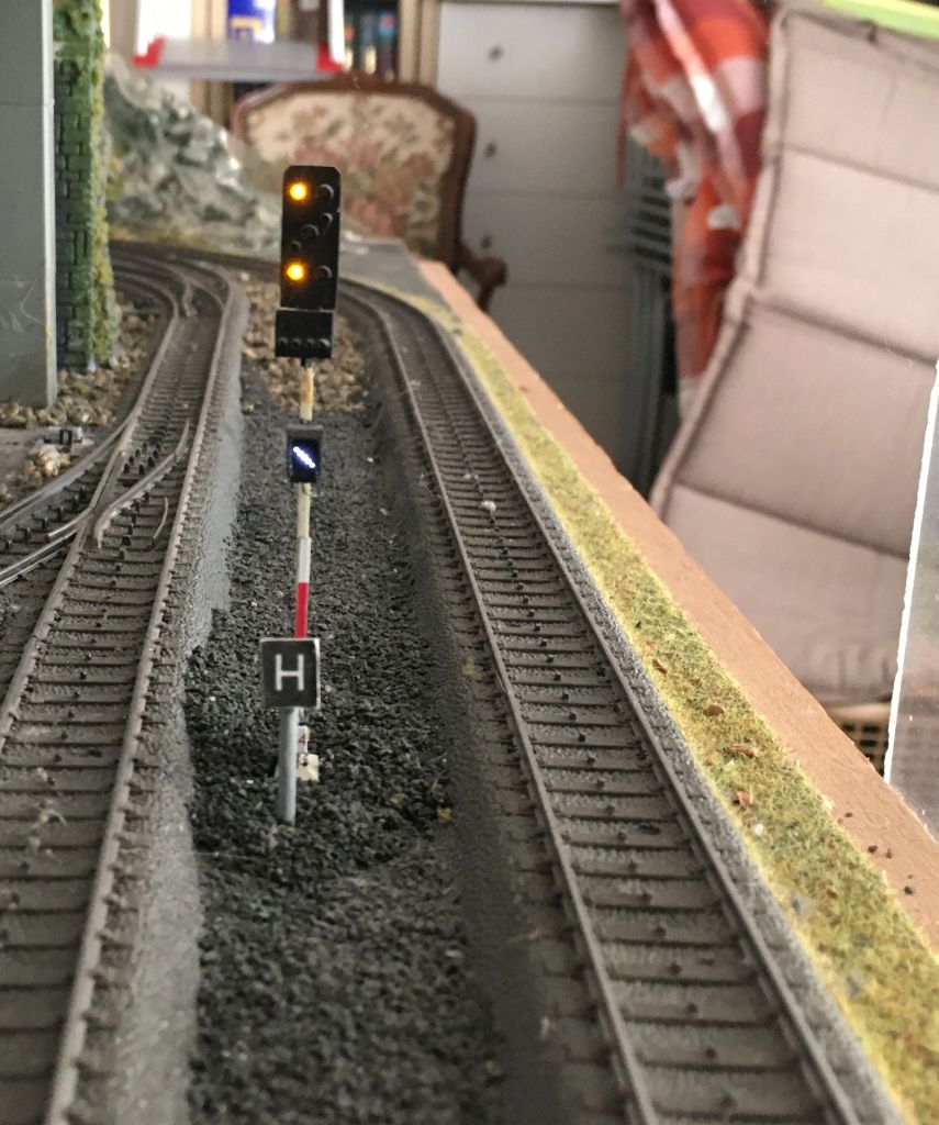
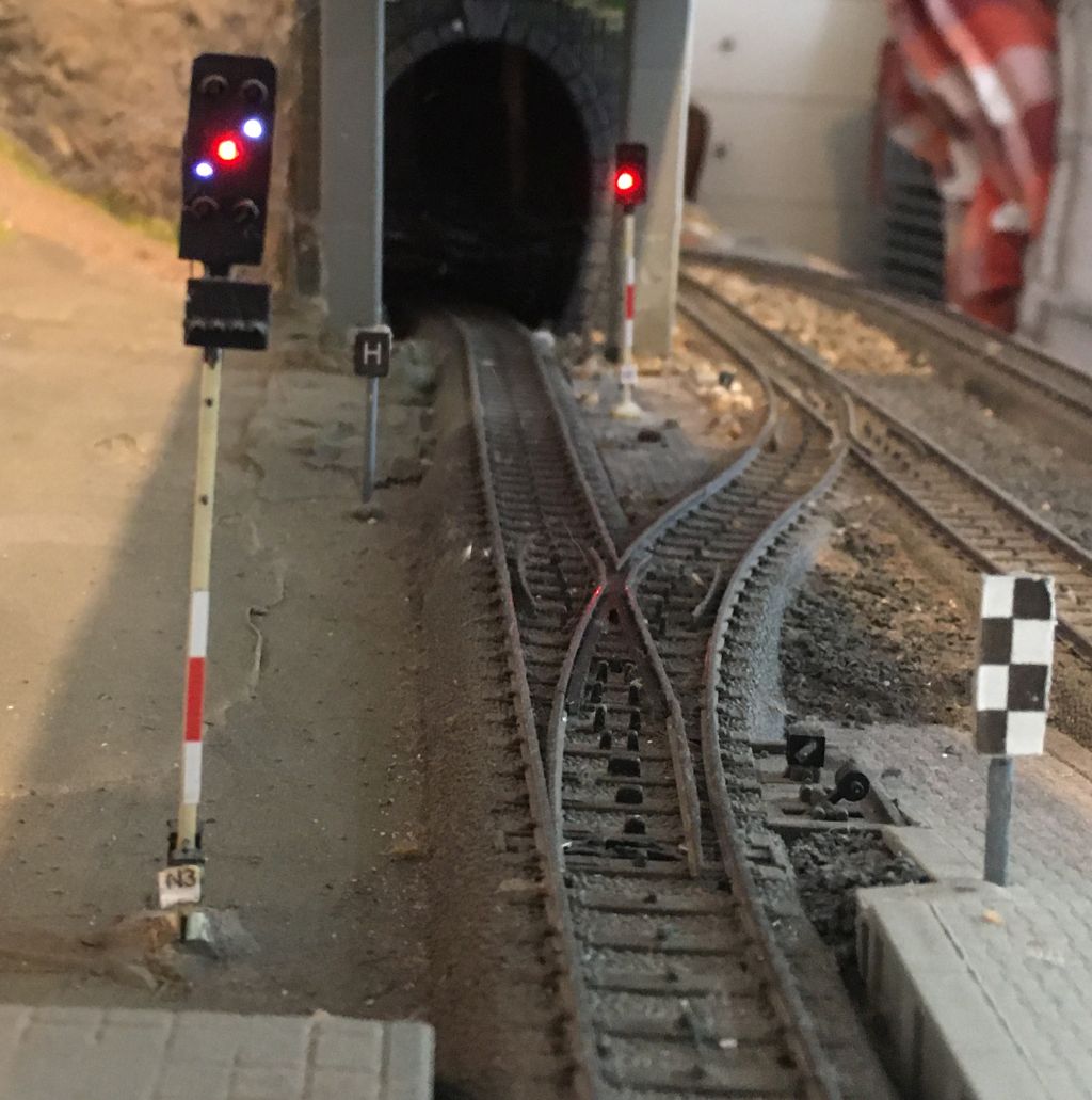
Point W5 is set to straight, so S1' (in the background) serves as
exit signal. In this case, S1 (in the foreground) is meaningless and is
operationally switched off. To distinguish it from a failed signal, it
displays a marker light (Kennlicht). A train may thus proceed past the point until the H board which is just in front of the signal S1'. |
  |
Exit is clear as signal S1' (in the background) displays Hl 1 (clear-expect clear) and point W5 is set to straight. As before, signal S1 has no operational meaning when W5 is set to straight, and therefore displays a marker light. |
  |
The same situation, but with the point W5 set to diverging. A halting train must therefore stop in front of the signal S1 right at the platform end, so S1 is now displaying aspect Hp 0 - stop. Since S1 is exceptionally placed to the left of the track, a Ne 4 chequerboard sign is used to indicate that the signal is not in its usual position. |
  |
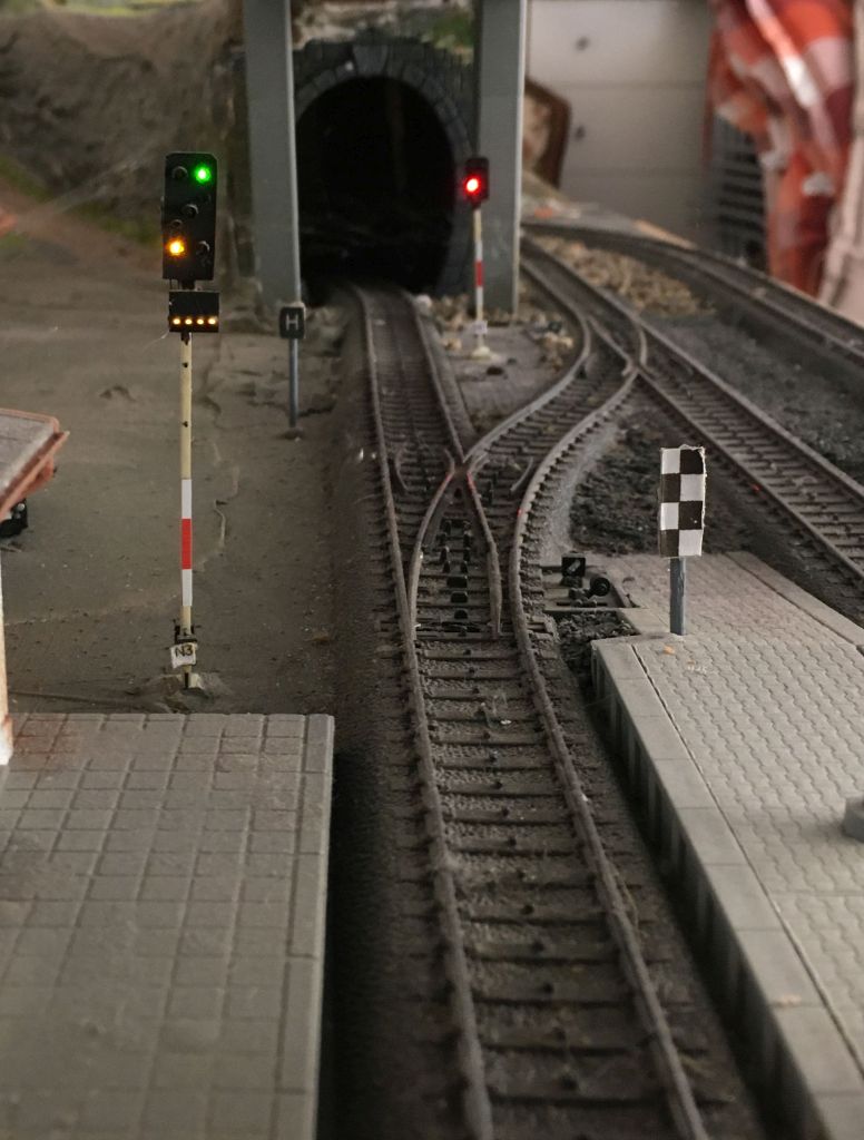
Exit is clear over diverging point W5, the next block signal (not
visible in this picture) will show stop. The lower amber plus
the amber bar indicates a speed limit of 60 km/h, and the upper amber
light indicates that the next main signal is at stop. Hence the signal S1 displays aspect Hl 12b - clear 60 with km/h, expect stop. The point in advance (W7) may lead the train onto either track 2 or 3, but since we first have to pass diverging point W5, the speed limit of 60 km/h is the same for either exit. Remember that German railways do not use route signalling. |
  |
Same situation as above, but the next main signal is at clear, which is indicated by the upper green light. Signal S1 displays aspect Hl 3b - clear with 60 km/h, expect clear. |
| exiting from track 2 | |
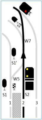  |
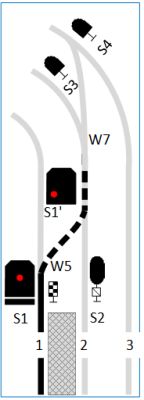
Exit from track 2 is clear, and point W7 is set to straight, i.e.
onto the regular (right) track of the outer loop. The next block signal S4 is at
Hp 0 - stop. Our exit signal S2 displays an amber light below without any bar, which means slow 40 km/h, and the upper amber light tells us that the next signal is at stop, so we see aspect Hl 12a (clear with 40 km/h, expect stop). |
  |
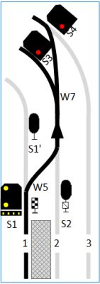
Now point W7 is set to the lesser curved track, leading onto the track no. 3 (which
is the right track of the loop line). Since the lesser curved track allows for a higher speed, the amber light with the green bar tells us that we are allowed to pass this signal with 100 km/h, and the upper green light indicates that the next signal is at clear. This is aspect Hl 2 - clear with 100 km/h, expect clear. |
  |
Now we are exiting from track 2, and point W7 is set to the stronger
curved track, i.e. onto the left (counter) line. The next block signal (not visible, it is just behind the bend) is
at stop. We stay on track 2, which is the counter line, so the
Zs 6
counter line signal beneath the Hl signal is lit. The lower amber light of the Hl signal indicates a speed limit of 40 km/h, while the upper amber indicates that the following main signal is at stop, so the aspect displayed here is Hl 12a - clear with 40 km/h, expect stop. This is the same aspect as when exiting onto the regular track, just this time with the counter line signal lit. |
  |
The same situation, but the next signal is at clear, so we see
aspect Hl 3a - clear with 40 km/h, expect clear. The speed after this signal is still restricted because the inward curved point (visible in the background) is set to the stronger curved track (which is the reason for the lower speed limit). |
 |
These are the signals S3 (track no. 2) and S4 (track no. 3) showing Hl 1 - clear, expect clear and Hp 0 - stop. |
 |
Signal S1 at Hp 0 - stop, but shunting is allowed by displaying the two white lights, which are shunting signal Sh 1. |
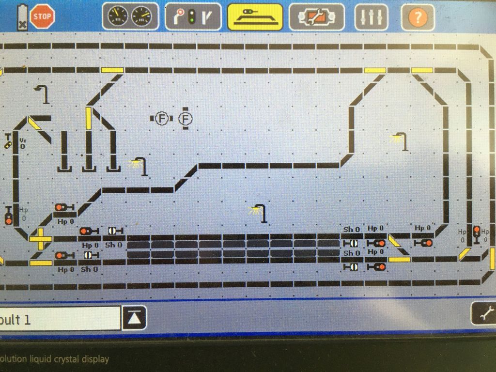 |
All the signals are controlled by Viessmann digital decoders which
in turn are controlled by an ESU Control Station. The Hl signals are
those to the lower right of the display. The shunting signals are controlled directly and are not driven by the relay logic. |
 |
A part of the relay logic using bistable relays and diodes. I use one bistable relay for each input (exit clear on tracks 1 and 2, and points 5 and 7) as well as some more logic for the Hl aspects including the bars, the marker light and the Zs 6 counter line signal. |
For the Hl signals, I built a separate logic which is using bistable relays. The logic simply takes the controls for the points W5 and W7 as inputs as well as the information whether the exit from track 1 and/or track 2 is clear, and the setting of the block signals S3 and S4, and then drives the output signals which are necessary to display the correct aspects at all the Hl signals.
 home home |
 model
railway model
railway |
 email email |
 pictures pictures |